 Subscribe! Subscribe!

My latest posts can be found here: Previous blog posts:
Additionally, some earlier writings: |
Introducing the contextOccasionally someone comes to me and says that they have a polynomial time algorithm for solving an NP-Complete problem. More specifically, someone came to me and said they could Graph Vertex Three Colour (G3C) in polynomial time. They'd tried lots of example, and it always worked.
So I produced a graph which was such that three colouring it would factor the challenge number RSA-220: Had they come back with a colouring then we would have factored RSA-220 and that would get a lot of attention, and prove that they had something really interesting.
As mentioned elsewhere, the problem is that random instances of an NPC problem are almost always easy (for some definitions of the terms random, instance, problem, almost always, and easy). So on this page we will see how to make a graph such that three colouring the graph factors a number. We start with long multiplication ...... base 2. So here is 23 x 13, or 10111 x 1101:
            1 0 1 1 1
              1 1 0 1
           -----------
            1 0 1 1 1
          0 0 0 0 0
        1 0 1 1 1
      1 0 1 1 1
     -----------------
    1 0 0 1 0 1 0 1 1
... which is 1+2+8+32+256 = 299, which is right. Good. Now, skew the middle table to become a rectangular grid, and write the second number, 13 (which is 1101 (base 2)), vertically down the left side, least significant digit at the top. Like so:
             1 0 1 1 1
           +-----------+
  LSB -> 1 | 1 0 1 1 1 |
         0 | 0 0 0 0 0 |
         1 | 1 0 1 1 1 |
  MSB -> 1 | 1 0 1 1 1 |
I'm ignoring taking the total. You can see that each cell is the logical AND of the column head and row label. Now we open it up and put back the idea of the addition. Remember, we skewed the table to make it rectangular, so the lines of addition have become diagonals:
       1 0 1 1 1
     +-----------+
   1 | 1 0 1 1 1
     |  \ \ \ \ \
   0 | 0 0 0 0 0  r0
     |  \ \ \ \ \
   1 | 1 0 1 1 1
     |  \ \ \ \ \
   1 | 1 0 1 1 1
     |  \ \ \ \ \
Here I've marked in the lines of addition - we add the number of 1's in each of those lines, and the result (possibly with an extra carry) comes out the bottom row. I've put "r0" at the LSB of the answer. Examining each cell.A Full-Adder takes three binary digits and outputs a SUM and CARRY. The number of 1's received is 2xCARRY+SUM, where each of SUM and CARRY are either 0 or 1. So here is a single cell to consider:
      X     Y
        \----|----+
    ... |         | ...
    ... |    Z    | ...
    ... |         | ...
        +----|----\
           CARRY   SUM
X and Y come from the cells above-left and above, and Z is the AND of the digits heading the row and column. The cell then produces a SUM and CARRY as shown. Glueing lots of these together makes a long-multiplication circuit.
Emulating circuits with graphs ...Technical preliminaryWe start with a technicality. In what follows we are going to assume that for a given graph we can force vertices to be of particular colours, or chosen from a particular set of colours. Here's how we accomplish this.
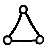
To do this, in our graph we ensure that there is, somewhere, a triangle of vertices. When we three-vertex colour, these must all be different. So let's suppose we colour with Red, Green, and Blue - each of those colours must appear on our triangle. Now whenever we succeed in three colouring our graph, whatever the top vertex of our triangle is coloured, be it Red, Green, or Blue, relabel that colour everywhere as "*". Whatever the bottom left is coloured, relabel it everywhere as "0", and whatever the bottom right is coloured, relabel it as "1". We now have a colouring using the colours "*", "0" and "1".
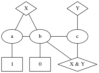
If we want a particular vertex to be a digit, then we can connect it to the top vertex of our designated triangle, and now it can't be "*", as required. So in what follows, by using this technical device, we can specify that some vertices are digits, and some vertices have specific labels. Our first logic gate ...Well, actually our second. Our first gate is a simply triangle with one vertex forced to be "*". The other two vertices must then be digits, so if we think of one vertex as the input and the other as the output, we have a simple NOT gate.
So:
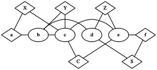
A "Full Adder" graph
Examining this graph closely (which I don't necessarily recommend you do unless you really want to) we find that when X, Y, and Z, are each coloured either 0 or 1, the output nodes C and S are the Carry and Sum respectively. An interesting point to note is that there are no nodes forced to be "0" or "1". That's because the Full Adder is independent of changing all 0's for 1's and 1's for 0's - an observation that's reflected in the construction of this graph. This is in contrast to the AND gate, where "0" and "1" do not have symmetrical roles, and therefore appear as literals in the graph. Indeed, changing the "0" and "1" turns the AND graph into an OR graph. It's not really relevant, but a natural question to ask is whether this is the smallest possible Full Adder graph. Not important, but a curiosity.
Pulling it all together ...
So what were 0s and 1s in the interior of the multiplication table are now full-adder cells. One of the inputs to the cell comes from the North-West, one of the inputs comes from the North, and the third input is the logical AND of the corresponding input bits from the number we are multiplying. The Carry is sent Southwards, and the Sum is sent to the South-East. In each case they become the inputs for the neighbouring cells. Thus we have created a cell to be an internal bit of the multiplication table by using a Full Adder, and having the Z input as the result of the AND of a bit from each multiplicand. The carry, C, from one adder is identified with the Y input of the cell below, and the sum, S, is identified with the X input of the cell to the lower right of it.
The vertical double bars and diagonal double bars are identifications of the corresponding vertices, C of one with Y of the other, and S of one with X of the other. But this is, in effect, a complete graph to multiply two 2-bit numbers to get a four bit result. It's clear how the graph can be extended to be able to multiply larger numbers. So now we have a graph such that forcing the vertices across the top and left to be suitable 0s and 1s, three colouring it results in the product appearing on the vertices down the right side. We have a graph that can perform multiplications. Using the graph to factorSo every legal colouring of this graph corresponds to a multiplication. We can set the input vertices to what we want, colour, and read off the result from the output vertices. But equally we can set the output vertices to be whatever we want, and then a legal colouring will have the input vertices as factors of the number. If we force the output vertices to be 1001 then there is a unique colouring, with all input vertices 1. But if we force the output vertices to be 1000 there is no valid colouring, because we only have two bits in each input, and 8 can only be factored as 2 times 4. Similarly, if we force the output vertices to be 0111 or 0101 there is no valid colouring, but if we force them to be 0110 then there are exactly two valid colourings. It's interesting that changing a few edges around can make such a difference to the exact count of the number of colourings. Now we can create a larger graph, one that's large enough to accommodate any number we wish to factor. Suppose we want to factor RSA-768, a number with 768 bits. One factor can have at most 384 bits, the other factor can be limited to having at most 767 bits, and so we can create an appropriate graph and force the output bits to RSA-768. Now a legal colouring will give us a factorisation. We know that there is exactly one colouring for this graph, because there is one factorisation of the "output" vertices. But small changes of the output vertices can lead to large changes in the number of colourings. There are primes at a small Hamming distance from RSA-768, and they give no colourings, and there are numbers that are quite smooth, which give several colourings.
ImplicationsThe broader implication is more interesting. We constructed a graph that performs a specific calculation, namely, multiplication. But the fact that colouring doesn't intrinsically have a direction means that we can then effectively run the calculation backwards, starting with the result we want, and then finding the inputs that create that result. We can now move that up a notch and talk about NP-Completeness. Given a specific Turing Machine we can create a combinatorial circuit of gates that implements it. Given the constructions described above, this gives us a complete proof that G3C is NP-Complete. In outline it goes like this.
CommentsI've decided no longer to include comments directly via the Disqus (or any other) system. Instead, I'd be more than delighted to get emails from people who wish to make comments or engage in discussion. Comments will then be integrated into the page as and when they are appropriate. If the number of emails/comments gets too large to handle then I might return to a semi-automated system. That's looking increasingly unlikely.
|


 Suggest a change ( <--
What does this mean?) /
Send me email
Suggest a change ( <--
What does this mean?) /
Send me email